OSCILLATORS - INTRODUCTION
- Many electronic devices require a source at a specific frequency, which may range from several MHz. This is achieved by an electronic device called an oscillator.
- The oscillator is an electronic device that generates an AC signal with the required frequency, required amplitude, and required waveshape.
- In radio and television receivers, oscillators are used to generate high-frequency carrier signals. Oscillators are widely used in_radars, electronic equipment, and other electronic devices.
Oscillators are broadly classified into two types
They are
i)Sinusoidal oscillators
ii) Non-sinusoidal oscillators (Relaxation oscillators)
- The sinusoidal oscillators are used for sinusoidal signals with required generating only frequency and required amplitude.
- The non-sinusoidal oscillators are used for producing non-sinusoidal signals like square, rectangular, triangular, or sawtooth signals with amplitude and required frequency.
Classification Of Oscillators
Oscillators are classified into the following
different types
(A) According to the waveform generated
(i) Sinusoidal oscillators
a) LC oscillators, and
b) RC oscillators
(ii) Non-sinusoidal oscillators (Relaxation
oscillators)
a) Square wave generator
b Rectangular wave generator
c) Sawtooth wave generator
d) Triangular wave generator
(B) According to the fundamental mechanism used
Negative resistance oscillators
(i) Feedback oscillators
(C) According to the frequency generated
(i) Audio Frequency (AF) oscillators
(ii) Radio Frequency (RF) oscillators
(ii) Very High Frequency (VHF) oscillators
(iv) Ultra High Frequency (UHF) oscillators
(v) Microwave oscillators
Condition for oscillations (Barkhausen criteria)
Barkhausen criteria are the statement that gives
the essential condition for maintaining self-sustained oscillation.
The block diagram of a feedback amplifier is shown in fig.
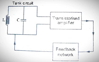
General form of LC oscillator
The block diagram of an oscillator is shown in fig.
It contains
1) tank circuit
2) transistorized amplifier, and
3) feedback circuit.
i) Tank circuit
This circuit contains an inductor and a capacitor, connected in parallel form. It is the circuit that produces oscillations of a desired frequency. It is also called an LC circuit or resonant circuit.
A simple tank circuit with an inductor and a capacitor, connected in parallel is shown in fig.
This circuit can produce an AC emf with the required frequency. The frequency is determined by the values of L and C.
Basically, L and C are energy storage components. The capacitor stores voltage in an electric field. The inductor stores are current in a magnetic field. Therefore the capacitor opposes the sudden variation of
voltage and the inductor oppose the sudden variation of current.
At the initial level, the switch is in an open state and hence the voltage across the tank circuit is zero.
When the supply voltage applied to the capacitor is ON, It charges the capacitor towards its supply voltage with the polarity, as shown in fig. This variation reduces the first quarter cycle of sinusoidal signals. When the switch is closed as shown in the fig., the capacitor will discharge through the inductor, hence the inductor stores the energy in the form of currency in a magnetic field.
The discharging effect of the capacitor produces the second quarter cycle of the sinusoidal Signal. When the capacitor is fully discharged, the voltage across the tank circuit is zero.
After the full discharge of the capacitor, the current that flows through the inductor is stopped.
Now the magnetic field in the inductor is also collapsed and produces counter emf. So the inductor will leak the Current through the capacitor.
The capacitor again charges the voltage with a polarity (opposite direction) marked in fig. This variation is negative and produces the third quarter cycle of the sinusoidal signal.
During the discharging period of the inductor, the energy is stored by the capacitor in voltage form.
Again the capacitor discharges the already stored negative voltage, through an inductor, as shown in fig. During this period the inductor again stores the energy in the form of current. This variation produces the fourth quarter cycle of the sinusoidal signal. All the actions are repeated and produce a continuous sinusoidal signal.
The charging and discharging effects of the capacitor and Inductor produce a continuous
sinusoidal signal at the output of the tank circuit. According to the losses of the inductor and capacitor, the amount of signal is reduced with the increase of time. Hence the voltage becomes zero in a specified time. This effect produces a damped oscillation.
ii) Transistorised amplifier
A transistorized amplifier receives the DC power from the battery and changes it into an ac power for
supplying to the tank circuit. In order to produce undamped oscillations, it is necessary to apply the required amount of energy to the tank circuit at appropriate time intervals. This effect overcomes the losses of capacitor and inductor. This is done by using a transistorized amplifier.
The energy applied to the tank circuit at the appropriate intervals means that the energy applied to the tank circuit is the same as the frequency of the signal Produced from the tank circuit. Hence the signal from the tank circuit is applied to the input of the transistor in the amplifier. Then a fraction of the amplified output signal is applied to the tank circuit, for overcoming the losses Generally CE amplifiers are used for this purpose.
iii) Feedback circuit
Positive feedback is very essential in oscillator circuits. The feedback circuit gives the correct amount of energy (B) to the tank circuit. The amount is properly set for maintaining barkhausen
criteria. The generally used CE amplifier produces 180° phase shift and the feedback circuit produces
another 180°phase shift for maintaining sustained oscillation.
Actually, this circuit feeds a part of collector energy to the tank circuit incorrect phase to ai
Oscillation.


Post a Comment