RECTIFIER
INTRODUCTION
Mostly all electronic devices require D.C. power for their proper operations. D.C. batteries are used for moving vehicles and rarely in commercial appliances, but they are costly and require frequent charging or replacement. So we can get D.C power from AC lines by using a regulated DC power supply. It consists of a transformer, rectifier, filter, and regulator.CLASSIFICATION OF RECTIFIERS
The unidirectional characteristic active element, the diode is used for this purpose. The rectifier converts an AC signal into a DC signal. There are three different types of rectifiers, namely(a) Half wave rectifier
(b) Full wave rectifier
(c) Bridge rectifier
HALFWAVE RECTIFIER
This rectifier converts an AC input voltage into DC pulsating voltage for only one-half cycle of theapplied voltages. The circuit diagram of a halfwave rectifier is shown in fig. This circuit contains only
one diode. So the output contains only positive half cycles of the input. During the positive half cycles of the input signal, terminal A is positive with respect to terminal B Now diode D conducts in forward bias. So the current flows from terminal A to B through diode D and load resistor R. Hence input voltage is fully dropped across the load resistor R.
During the negative half cycles of the input signal, terminal EB is positive with respect to terminal A.
Now diode D conducts in reverse bias. So no current flows through the diode and load resistor. Now the output voltage is zero. In this circuit, the output contains only the positive half cycles of the input signal. So it is called a half-wave rectifier. The input and output waveforms are shown in fig.
 |
| Input and output waveforms of half wave rectifier |
In this rectifier, the diode conducts only the positive half cycles of the input signal. So the current flows through the transformer is in only one direction. Hence DC saturation of the transformer takes place. The peak inverse voltage of the diode should be at least equal to VM.
FULL-WAVE RECTIFIER
A full-wave rectifier contains two diodes, so these diodes conduct a full cycle of the input signal. Thecircuit diagram of a full-wave rectifier is shown in fig. This rectifier uses a center tap transformer,
which produces two equal magnitudes of voltages at the opposite terminals. One end terminal voltage is out of phase with the other end terminal voltage with respect to the center tap terminal.
During the positive half cycles of the input terminal A is positive, and B is negative with
voltage, respect to terminal O. Now the diode D, conducts in forwarding bias and diode D,
So the current I, flows from terminal A to the load through diode D No current flows through the diode D, conducts in reverse bias. Similarly, during the negative half cycles of the
input voltage, terminal B is positive and A is negative with respect to terminal O. Now the diode D conducts in forward bias, and the diode D conducts in reverse bias. So the current I flows from terminal B to the load through the diode D,. The currents i1 and i2 flow through the load in the same direction. If the magnitude of applied voltage at terminal A is equal to terminal B voltage, the current i1 is equal to i2. The input and output signal waveforms are
shown in fig.
 |
| Input and output waveforms of full wave rectifier |
In this rectifier, the two diode currents flow in opposite directions through the transformer. So D.C.
saturation of the transformer does not take place. The peak inverse voltage of the diode should be at least equal to 2Vm.
BRIDGE RECTIFIER
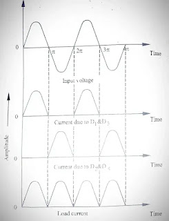
The bridge rectifier is also a full-wave rectifier. It Contains four diodes and an ordinary step downtransformer. The circuit diagram of the bridge rectifier is shown in fig.
During the positive cycle of the input signal, terminal A is positive with respect to terminal B. Now the current flows through D,, RL and D Thus the input signal is fully dropped across the resistor RL. Now the diodes D, and D are not conducting. During the negative half cycle of the input, terminal B is positive with respect to terminal A. Now the current flows through D,, RL and D Thus the
the input signal is also fully dropped across the resistor RL.
 |
| Input and output waveforms of bridge rectifier |
Now the diodes D, and D, are not conducting. During both half-cycles, the current flows through
the load resistor RL in the same direction. The input and output signal waveforms are shown in fig. The
peak inverse voltage of the diode is equal to Vm.
RECTIFIER APPLICATIONS
i)DC motor drivesii) Welding power supplies
iii) Uninterruptible power supplies (UPS)
iv Industrial systems that require DC voltage


Post a Comment